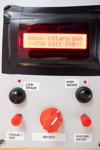
Just show me the user manual! Now I also want to make a f stop timer!
Long winding introduction to f-stop printing and LEDs for Multigrade papers.
During a (APUG) analogue workshop back in 2013 i Larvik, one of the guys (Trond) talked about f-stop printing for timing paper exposure in the darkroom and demonstrated his RH design “StopClockProfessional”. And Wow! Note there is nothing magic with timing the exposure using f-stop that a regular linear timer not will do, as they both expose the paper to light for a specific time. However when using the f-stop method the exposure time is expressed in stops, same way as when you make the exposure on film with a camera. Think of photographic paper as film 🙂 On the camera / shutter you may increase/decrease the exposure in stops going from f/2.8-4 to f/4 to f/5.8 etc. or 1/60 to 1/125 to 1/250 to 1/500Sec. For f-stop printing the base exposure of 1 step is 2 seconds, thus 2 Stops is 4 seconds, 3 stops is 8 seconds.. See the similarities? eg doubling when going up and half when going down..
OK, now but WHY is this useful? And not just a added layer of complexity (or mystery?) to a craft already difficult enough and not to mention exercised in the DARK!!
Well, think about making test-strips in order to determine correct exposure for the print and its various sections (expose for the highlights) when using a linear timer you might make test strip like this:
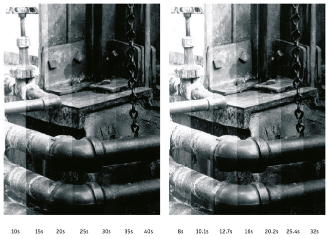
Linear test strip expose 10 – 15 – 20 – 25 – 30 – 35 – 40 seconds..
Now what are the difference between the individual strips? 10 to 15 is 50% change, 15 to 20 is 33% change, 20 to 25 is 25% change, 25 to 30 is 20% etc.. Not exactly evenly spaced are they? (large at the start then smaller and smaller)
f-stop test strip expose 8 – 10.1 – 12.7 – 16 – 20.2 – 25.4 – 32 Seconds, where the difference between the individual strips is a evenly and constant spacing of 1/3 stop. The test strip may be described as 3 steps as base exposure with increments of 1/3 steps.
e.g. 2 – 2 1/3 – 2 2/3 – 3 – 3 1/3 – 3 2/3 – 4.
See teststrips below, 25s to 40s on linear vs 8 to 32 on f-stop (Source: Way Beyond Monochrome, page 24)
f-stop printing: This enables you to judge difference in required exposure for the various parts of the image in stops, which again are relative to each others, regardless of enlargement ratio. Just find the new base exposure. If you have access to a copy of the excellent book Way Beyond Monochrome, have look at the chapter “Timing print exposures” page 23-27.
Still confused?? Check out this f-stop primer from RH designs, or sit back and enjoy this documentary video of an interview with Gene Nocon, the inventor of f-stop method.
I was keen to try this approach in my own darkroom practice and given a previous knowledge and interest for Arduino mikrocontrollers, not to mention a large stock of “spares” and extras from ebay after a other few Arduino projects.. Now how hard could it really be? Just simple math and switching on/off of the enlarger for the right amount of time. Yeah right…! But quite quickly I found William Brodie-Tyrrell´s brilliant open source f-stop timer, and after some tinkering I had my first f-stop timer up and running. Once you have grasped the concepts its easy and brilliant. I have since then ordered the printed circuit board (PCB) from William Brodie-Tyrrell and built 2 more f-stop timers to that the design. Highly recommended.
PS. No, you don’t need a f-stop timer to this, I have friends who do the the math in their head.
At the time (winter 2014) I had (and still have) a large Durst 138s with a CLS 301 colorhead which worked well with the f-stop timer. However as spring 2017 came, the enlarger was starting to make trouble by tripping the house main fuse several times and smelling of burnt cable insulation… it has 2 x 300 w bulbs thus it requires a substantial power ON current and generates a LOT of heat. Note the Durst came to me winter of 2006, before that it had been in service in Norways premier photo lab since 1970!! i.e. it had a working life of 36 years before it came to relax with me!! It worked and still works flawlessly, over engineered or just the way things should be?
It was then time to look seriously into LEDs, and since I had started dabbling with split grade printing, why not with color LEDS? Split-grade (The Online Darkroom, Les McLean, Way beyond Monochrome), using green LED (or filter #00/max Yellow ) and blue LED (or filter #5/max Magenta) in two separate exposures, one hard contrast for “good” blacks and one for soft contrast enabling desired highlight separation, the middle tones being taken care of “kind of by themself”. Sounds complicated? But once you have learnt the method, it does not use more more paper or takes more time than the regular start at 2.5 Grade, and then adjusting grades to get the blacks right and the time to get the highlights right. But the real brilliance of the method is linked to exposing different parts of the print with different grades or a mixture of grades. This enables printing really difficult negatives, and I have bunch of those!
“In photography there can be many tools and methods used to achieve the final result. As with many art forms, each method has its devotees and denouncers. While this makes for entertaining discussion, it does rather miss the point. Split-Grade printing is one of those alternative techniques that works all of the time for some and some of the time for all.” Source: Way Beyond Monochrome, link above.
Google found me plenty of excellent sources for DIY LED heads on the web, these two are the main inspiration:
- Tripping Through the Dark – LED Head by Larry
- JBH Photo – Designing & Building an LED VC Enlarger head (pdf)
Tested this on my Focomat II with a five RGBW LED setup using the William Brodie-Tyrrell f-stop timer and an Arduino LED controller switching between Green LED (Grade 00), Blue LED (Grade 5) and a mix of both to achieve intermediate grades. I used the Red LED as a safe focus light and the combination of all three to get maximum brightness for focus light. Larry at Tripping through the dark had made a modified copy of the William Brodie-Tyrrell f-stop timer to do split grade printing, available at GitHub. I tried this with my set up and managed to compile the Arduino sketch (C and C++ like code) but was unable get the code to run for more than 10 seconds, definitely my fault since I was using a different display library (I2C display) and the code is way beyond my coding skills.. (I learnt non-compiler i.e. straight to memory machine code assembly for the 6502 microprocessor back in 1981 and Pascal in 1985) Thus I made a simplified version to suit my needs and compatible with my skill level :-). As a result the timer currently does, in four different modes:
- Dual channel 7 memory slots f-Stop split grade timer mode with built in quick soft and hard teststrips, drydown factor etc
- Dual cannel 7 memory slots Linear split grade timer mode with built in soft and hard teststrips, drydown factor etc
- Standard Linear timer mode with freely adjustable times and grades.
- External timer input mode with changeable grades to utilize the original William Brodie-Tyrrell f-stop timer or a timer like the RH Design “Stop clock” as the timer input.
Just show me the user interface! Now I want to make a f stop timer!